
The plot thickened as I tested the power supply. I checked for voltage on the outputs and discovered it was putting out 27V instead of 24V. Not to worry I thought, lets see if it turns on. Connected it up and the relay inside clicked, no meter lights turned on though. The power light on the power supply was dead, I reasoned there could be faulty bulbs in the meter bridge also. Worryingly, it made a buzzing noise when I turned it on, I started to worry about what I might find.
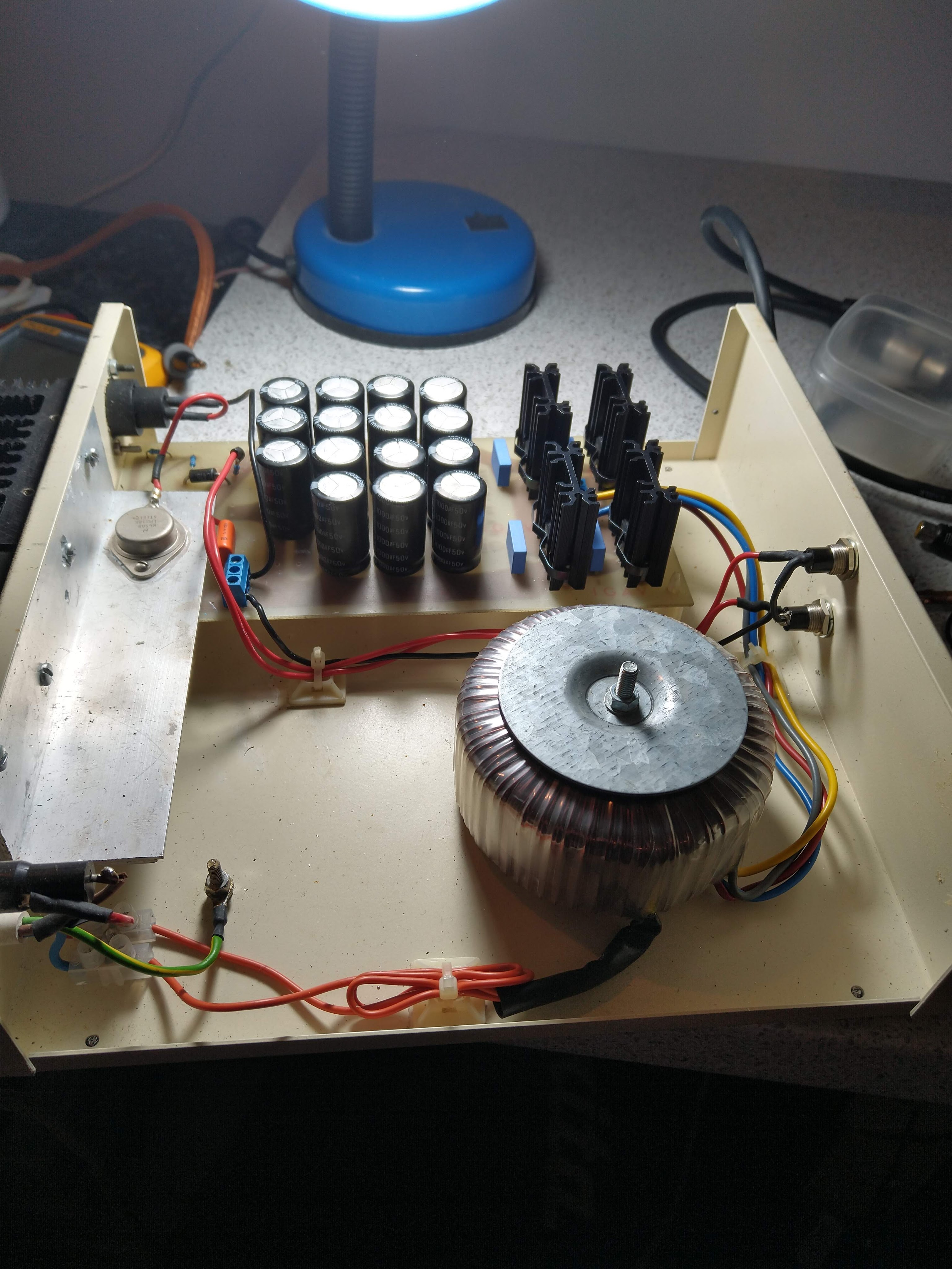

I then proceeded to take apart the PSU and give it a once over. The first thing was the plug was cracked, easy fix. Secondly, the power supply had been changed from the original at some point to a LM338 based design circa 1995. Whilst it initially looked like a professionally manufactured board, there were signs that this was a DIY job. For a start, the rear heat sinks were crudely fitted, it looked like these had been botched on as there was a right mess on the screws. Looking on the bottom of the PCB, I confirmed it to be home etched. Not an issue in itself, home etching is perfectly fine. If you know what you are doing. The basic layout was fine, however, it was not designed to be adjusted. It looks like this design was copied and adapted.

Finally, the negative of the secondary side of the transformer was tied to the primary sides earth. Yes you read that correctly, the mains earth was tied to the supply chassis. The DC circuit ground should NEVER be connected to the chassis if it is earthed on the primary side. One reason is that you can pick up mains hum through the chassis.
However, more pressing, if I plugged in when there was a fault condition it would be the equivalent of tying the secondary ground to the live mains, with the mixer forming one half of a current divider with your property’s earth impedance loop. This would cause AC back feed through the circuit and could potentially lead to electric shock, fire or catastrophic damage.
Whilst most earthing systems would shunt the majority of the excess current, this is not always the case. If your properties earth loop impedance was high you could have serious problems. I have seen properties Z readings go above 1K when the ground dries out around an earth rod, and then rather than a direct short to ground, you have a mixer forming a current divider with a 1K resistor.
Yes, RCD protection would help here but I’m fairly sure you want to avoid a 30 millisecond bolt of mains electric through your vintage console. That’s enough time to blow every transistor and give you a painful bolt. This was a potentially dangerous wiring fault and this did not fill me with confidence.
On balance then, it would seem that this power supply was built by someone who doesn’t know about electrical safety, and the plot thickened as after I removed this earth link. I started reading 29V on the output. Yes, it seemed that the reason for tying secondary ground to primary earth was was to try and drop the voltage down a little. It may have been the case that this dropped the regulated voltage down a bit during their initial tinkering. I wonder if the design is bad also.
Since this circuit had no option to fine tune the voltage it would need to have this section redesigned or modified.

There was evidence of scorching by a schottky diode and the reason for two power lights was a bit of a mystery. I think again they tried to make a voltage drop after the regulator to get the voltage nearer to where it needed to be. This is the only reason I could see for doing this. I could change the configuration to a single power LED and reconfigure the arrangement to make something stable and safe. I also noticed there was no output smoothing capacitor so we could definitely make some serious improvements to the supply design and its safety elements. I could reuse components but I am thinking about making a new pcb eventually.

The reservoir capacitors were configured in parallel to give 10,000uf, which would have been more relaible than a single 10,000uf capacitor, however, it is a bit overkill. Also there were two badly bulging capacitors which would give up eventually. These other caps would need to be checked regularly to ensure that they were not drying out.

So, without even opening up the console I discovered a dangerous wiring fault, DC regulation problems, bad caps, and strange attempts to control the volatge. I had the feeling I was going to be undoing the DIY handywork of someone who owned the console previously. I just hoped that they hadn’t gone too far that I couldn’t undo it. In any case I was going to potentially mod it so I wasn’t deterred, just worried about what I may find! If it was all original inside I wouldn’t necessarily tinker too much just for the sake of it. However, if I had a mangled channel or two, I could put these forwards for a makeover.
As it happened, I was able to find a set of schematics for power design using the LM338 regulator doing a a quick search. All it required was a couple of diodes, resistors and a trimmer resistor to form a feedback network that can be precision tuned. After looking at the mixer schematics its power draw was 2A at 24V DC. It was fairly easy to modify the power board to incorporate this control network and I tuned the voltage to my requirements.
The LM338 is rated to deliver 5A in this configuration, so it was not going to be taxed too heavily and the heat sink present was over specced, so I felt sure this was more than adequate. I replaced all the smoothing capacitors despite it being overkill, at the end of the day there may have been a good reason for this extra smoothing, but I’m not sure that if someone who ties DC ground to the primary earth should be trusted to make more nuanced decisions regarding capactitance. As it happens, this level of capacitance is would you would find on vintage amplifiers and given the weight of the DC load, its not going to hurt having more than required.
The heat sink was gargantuan and was covered in thermal paste. In that sense it would have been good enough to cool a server farm down. The LM338 can get quite hot in use so this over-specced part was more than adequate. Not sure about the gallon of thermal paste that got all over my hands, but regardless a good case of over engineering.

As for LEDs, I just removed them and kept one for a power on indicator. So that was fairly easy to sort out the PSU. Now on to the mixer itself.
