
Blast from the past
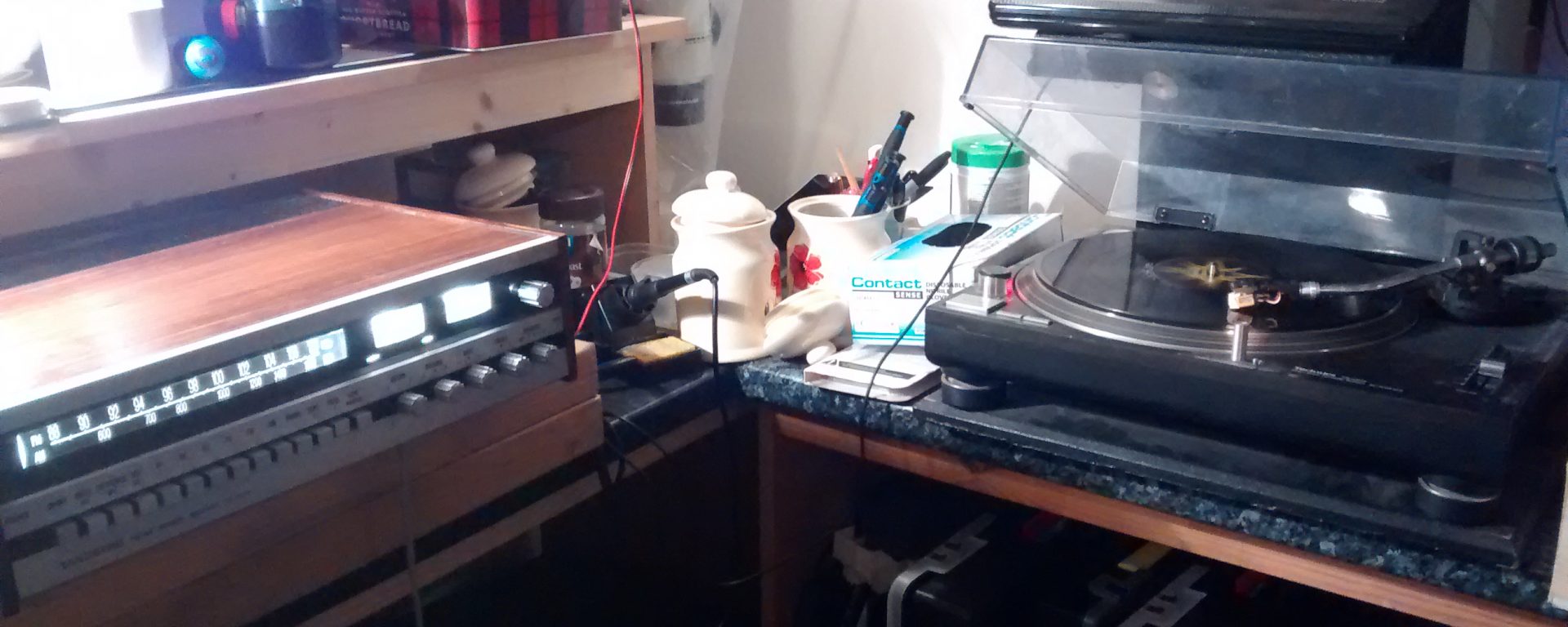
Vintage early 70’s Tandberg amplifier with germanium output transistors
I had this 1971 Tandberg amplifier in and it needed some serious TLC after years of neglect. Tandberg are a Norewgian brand who still made viusal equipment until recently, although they were bought out by cisco systems and the brand has been retired. I have not seen if they still make boutique amplifiers, but I am sure they don’t make them like this behemoth anymore!
Back in the 1970s, germanium transistors were being phased out in favour of their silicon counterparts. In this Tandberg there was a mixture of transistors but I was pleased to find the main power transistors were germanium.

Germanium transistors are quite leaky compared to their silicon equivalents, but there is a notable characteristic in sound difference. Like the vacuum tubes that preceded transistors, they have a distinct sound that is pleasing to the ears. The difference between germanium and silicon transistors is ever so slight but they sound slightly more transparent, and have a smoother sheen. Read in to that what you will! Audio is hard to describe with words alone, listening is the litmus test.
Analysing Amp Faults
Which brings us to the fault we had to rectify with this Tandberg repair. It had an intermittent fault on the right output, where there was a degree of crackling. This would normally appear after 15 minutes of use. Sometimes, I could run it for an hour and hear no distortion.

Some of theories I envisaged were a loose connection, a faulty thermal switch, or stray radio signals. Crackling on an audio circuit indicates electrical noise. This is mostly generated from intermittent contacts. The characteristic of this sound was that it was in the audio path, since even with no input connected, the crackling was still coming through the speakers.
This kind of fault indicates that noise is being made inside the amplifier. You may notice crackling when you operate the controls on an old piece of gear. This usually means the pot has dirt inside which produces an intermittent electrical contact. This is a sign that the component needs replacing.
Electronic circuits can easily pick up radio waves and amplify the signal causing noise. This can occur when using op-amps. However, since this amp had very few IC chips, I suspected this was not the culprit.
Dirty Terminals
In my experience, crackling can often mean an issue with the output board. Poor contacts inside audio terminals can cause problems such as this. After opening her up, I headed straight there and saw straight away that these terminals looked in bad shape. I re-flowed the joints with some solder and flux, and they came up well.

I also gained access to the input board and found the terminals there were in bad shape. I got some wire wool to the surface and I found they cleaned up nicely. After cleaning all the contacts I re-tested it and the issue was still present.
Upgrading Tandberg Lights To LEDs
The lighting circuit inside the amplifier had been fried at some point as all but two of the 13 bulbs had blown. These were from the days before LEDs, and used tiny bulbs. I was incredulous about tracking some down but was lucky in my hunt and discovered some tiny E10 screw in bulbs, and some tiny 3V glow lamps. These were installed on a simple AC circuit. I experimented with LEDs but found if I replaced more than one bulb, the rest wouldn’t work. I think this is because the neutral line was being rectified by the diodes and hence was stopping the remaining filament bulbs working correctly. It was impossible to replace some, it was either all LEDs or no LEDs.
In order to implement this mod I could have rectified the secondary feed off the transformer, using a bridge rectifier, and replaced the bulbs with diodes. However this would have meant re-routing the cabling off the secondary coil. In theory it shouldn’t cause an issue, but seeing as I could source the bulbs, I abandoned this project. However, for a little bit of work it should be possible to replace the LEDs. You could build the circuit off a breadboard and insert it in without removing the existing cabling to test it. You need to make the following modifications according to the schematic. I didn’t get round to implementing it, but this is a fag packet drawing of how I would modify the lighting circuit (switches on each light omitted).

Note the fuse should be changed from 5A to 200mA, and the common ground connection to the negative DC side of the bridge rectifier off each branch. This circuit only has a current draw of 10mA. You could drop the values of R1 and R2 to try and get 20mA, which will increase the brightness, however, a resistor and LED combo for each switch would prevent dimming as more lights are turned on, rather than having each branch run through a single resistor (R1 & R2). If dimming was a problem you would require say a 470R/330R for resistors 1 to 13.
Tracking the Crackling
I started digging around inside the amplifier. I scoped some of the components while the amplifier was live. This was in order to try and track down the source of the noise. I would not recommend that you try this without taking necessary precautions. You need to keep away from the 230V line and any wiring on the primary side of the input transformer. I scoped the signal line looking for any component displaying any noise. Everything seemed OK on the amplifier board.

I then turned my attention to the thermal switches. This amplifier had a thermal cutout switch in order to prevent overheating. I suspected that this may have a bad contact, but on testing it showed no resistance So, that is the amplifier section ruled out, and this left me with the switchboard and EQ/ Filter board. I started to scope around the EQ board and I found no issues, other than a little corrosion on the metal surface of a variable resistor. This was not in the signal flow anyway, and I found no fault here.
By this point I was starting to scratch my head as I was not finding any stage where crackling was introduced. As I moved the probe of my scope I caught a wire going to the radio signal meter. Immediately the crackling appeared. At last, I found the culprit! I traced the wire back to its origin and it was to one of the wires in a plastic terminal block. I took the board out to inpsect it and discovered on the underside that a previous attempt at repair had been made. The previous repair job involved scratching the solder mask off a large section of trace, for absolutely no reason. Furthermore, the solder job had not been completed properly and the solder had never run through the joint. Luckily, it was a simple case of re-soldering the wire and re-coating the exposed copper to prevent oxidation of the trace, which may damage it eventually. I put it on test and the crackling problem was gone.

This Tandberg was given a new lease of life and was a real joy to work on. After 47 years of service I hope it will continue to give great sound for many more years to come. I doubt anything made today would stand the test of time so well as this prime example of 70’s product engineering. I also doubt anything available today, even top of the range gear, would sound half as good as this vintage amplifier.

